بشیر بی Ø¢زار - Decoding Technical Information
Sometimes, when you look at a piece of information, especially something that seems a bit technical, it can feel like trying to understand a secret code. We have all been there, staring at a diagram or a set of numbers, wondering what it all truly means. It is, in a way, like trying to figure out a puzzle where every line and every symbol holds a very specific piece of the bigger picture. This kind of situation asks us to slow down and really pay attention to the small things that might not seem important at first glance, but actually tell us so much.
When you are working with things like machine parts or electrical components, the details on a drawing are not just there for decoration; they are the instructions. They tell you how big something should be, what kind of material to use, or how different parts fit together. Getting these details right is, in some respects, the whole point of the exercise. A tiny symbol or a single number can change everything about how a part works or if it even fits where it is supposed to go. It is a bit like following a recipe where one ingredient is missing, and the whole dish just does not turn out right.
This discussion is about making sense of those very specific symbols and notes you might see on technical documents. We are going to look at some common examples, like those strange circles with lines through them, or letters that seem to pop up next to numbers. By breaking down these pieces of information, we can, you know, get a clearer idea of what the original creator wanted to communicate. It is about moving from confusion to a real sense of knowing what is going on, which is quite satisfying.
- Paleseafoam Leaks Of
- The Enigmatic Journey Of Theo James A Star In The Making
- Himynamestee Only Fans
- Slang Eiffel Tower
- Aisah Sofey Leaked
Table of Contents
- What do those symbols really mean?
- Making sense of بشیر بی Ø¢زار in measurements.
- How can we read dimensions clearly?
- Getting to the core of بشیر بی Ø¢زار and design intent.
- What about specific annotations?
- Understanding بشیر بی Ø¢زار in drawing notes.
- Is there a trick to seeing the whole picture?
- Piecing together بشیر بی Ø¢زار for complete designs.
What do those symbols really mean?
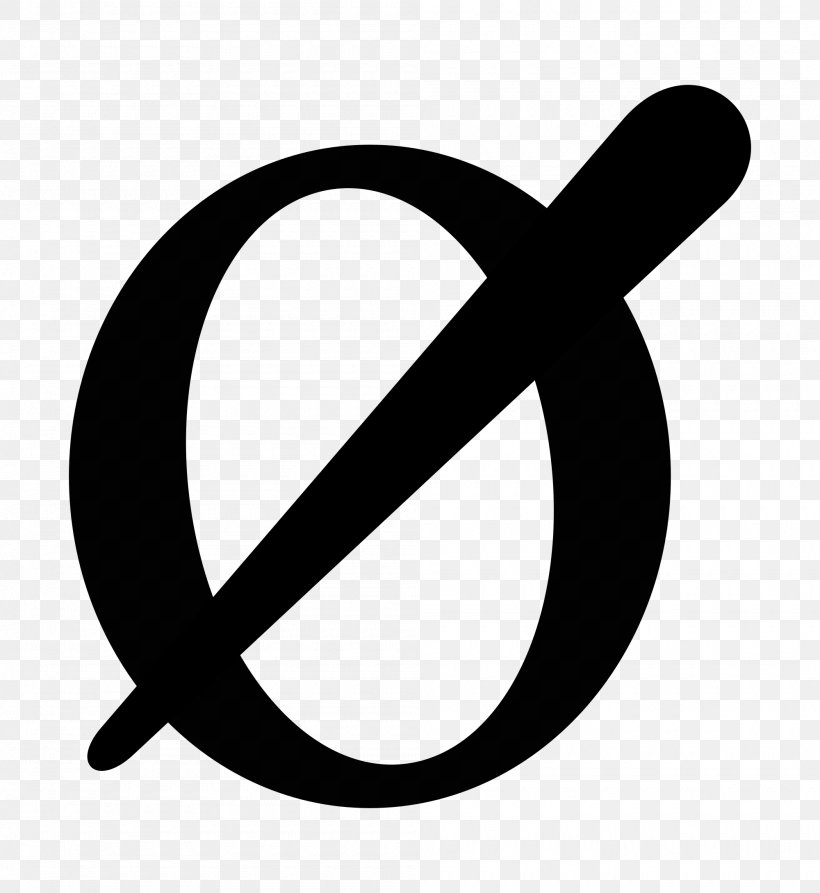
When you look at a data sheet for something like a stepper motor, you might see a measurement like "ø6" for the pitch diameter of a small gear piece. That little circle with a line through it, the "ø" symbol, is a common way to show that a number is referring to a circle's width, or its diameter. It is just a quick way to communicate something that would otherwise take many words to explain. You know, it is a universal sign in drawings. This symbol is pretty much everywhere in mechanical plans, and it always means the same thing, which is helpful.
Sometimes, you will see a number like "Ø 5" which means the size of a hole, like how big a drill bit you would need to make it. If it also says "thru all" next to it, that means the hole goes all the way through the material. It is a simple instruction that saves a lot of confusion, you see. Without that little extra phrase, you might wonder if the hole only goes part of the way in, which would change how the piece works completely. So, it is, like, a really important detail to notice.
Then there is the symbol "φ," which looks a lot like "ø" but is a bit different. On a drawing for electrical parts, like resistors, you might see "φ0.55mm" for the thickness of the wire coming out of the part. This symbol also means diameter. It is interesting because sometimes these symbols can look so similar, but they are used in slightly different contexts. You know, it is good to be aware of the small differences in how things are written down.
- Emily Compagno Husband
- Qatar Airways Iran Flights
- Emily Campagno
- Roma Downey Feet
- Bomb Threat At Atlanta Airport Today
Actually, when they give a wire thickness as "φ 0.55 mm" and then also say it is "24 swg," which is a standard wire size, it is a way to double-check the information. If 24 swg usually means a wire that is 0.559mm thick, and the drawing says 0.55mm, it is pretty close. This tells you that the numbers are consistent, or, you know, very nearly so. It helps you trust the information you are looking at, which is, basically, a big part of understanding the whole thing.
Making sense of بشیر بی Ø¢زار in measurements.
When you are trying to understand a measurement, like "ø12" on a drawing for a plastic piece that has an oval opening, you get that the "ø12" part means the circular width. But then there is something like "x25l" at the end, and that can really make you scratch your head. It is a very common situation to see parts of a measurement that are not immediately clear. That "x25l" might refer to the length of the oval, or perhaps the number of times that feature appears, or even some other characteristic that is not immediately obvious from just the symbols. It just shows that, you know, sometimes you need more context to truly grasp the meaning of every little bit.
The symbol for diameter, which looks like "⌀" and is a specific character on computers, is quite similar to the small letter "ø." In some fonts, they even look exactly the same. But in many other fonts, they are a little different. This can be a bit confusing if you are just starting out. It is important to know that even though they look alike, they are meant to be distinct symbols for a reason. You know, it is like how some letters look similar but mean different things. It is about paying attention to the details.
When you are new to mechanical design work and you are trying to get a project ready to send to a place that makes parts using computer-controlled machines, understanding these symbols becomes very important. Many places that do this kind of work rely on you providing clear and correct drawings. If the drawings are not clear, or if you misunderstand a symbol, the part might not turn out the way you wanted it to. So, you know, getting a good grip on these drawing languages is a big step in making your projects successful. It is, basically, how you communicate your ideas to the machines.
How can we read dimensions clearly?
Looking at an Autocad drawing, you might see annotations like "R1.25 typ" or "2xø1.0" or "ø1.25." These are all ways to give specific sizes and shapes. "R1.25 typ" means a rounded corner with a radius of 1.25 units, and "typ" means it is typical for similar features on the drawing. So, if there are other rounded corners that look the same, they probably have the same radius, which is pretty handy. "2xø1.0" means there are two holes, and each one has a diameter of 1.0 unit. It is a quick way to tell you about multiple identical features, you know, without having to write it out for each one. And "ø1.25" is just a single hole with a diameter of 1.25 units. These notes are, like, the language of the drawing itself.
Sometimes, when you are looking at how parts fit together, you might see a measurement and think it has something to do with how tight or loose the fit should be. It could be about making sure a round part fits into a hole just right, maybe specifying the smallest circle that goes around it or the largest circle that can fit inside it, to make sure the size is within acceptable limits. It is a bit like trying to fit a peg into a hole, and the drawing is telling you exactly how much wiggle room there is. You know, it is about precision, really. This kind of information is crucial for parts that need to move or connect without too much play.
When you are going through practice examples and you come across a diagram, you might have questions about how to understand the depth of a part. You might have already drawn the part on your computer, but figuring out the exact depth from the drawing can be a bit tricky. It is not always as simple as a single number. Sometimes, depth might be implied by other views or by notes that describe how the part is made. So, you know, you have to look at all the information provided, not just one piece. It is, in a way, like putting together a puzzle, where every piece helps you see the full picture of the part's shape.
Getting to the core of بشیر بی Ø¢زار and design intent.
When you are trying to create parts for something like a custom 3D printer, you might find specific components, like flanged lead screw nuts, that you want to use. But then you run into the problem of trying to read the measurements on their data sheets. It can be quite a challenge, you know, when the way the dimensions are written is not immediately clear. You might understand what a diameter is, but then there are other symbols or combinations of numbers and letters that just do not make immediate sense. It is, basically, like trying to follow a map where some of the street names are in a different language.
That "ø" symbol, when you look it up, really does mean diameter. It is a consistent symbol used across many different types of technical drawings and documents. Knowing this simple fact can clear up a lot of confusion right away. It is, you know, one of those fundamental pieces of information that helps you build a solid understanding of the drawing. Without knowing what that symbol means, you would be guessing, and guessing is not really what you want to do when you are making parts that need to fit together just right.
When a note says "thru all," it is there to make sure there is no question about the hole going completely through the material. This removes any uncertainty about whether the hole is shallow or deep. It is a very direct instruction that ensures the person making the part knows exactly what is expected. You see, these small phrases are there to prevent mistakes and to make the design intent absolutely clear. It is, in some respects, a very efficient way to communicate a lot of information with just a few words.
And when a drawing specifies a wire thickness using the "φ" symbol, like "φ 0.55 mm," and then also mentions "24 swg," it is a way to be extra precise. If you know that 24 swg usually has a diameter of 0.559mm, then seeing 0.55mm on the drawing tells you the measurement is very close to the standard, or, you know, perhaps a slightly different, more exact measurement for that specific part. It is like giving two different ways to confirm the same thing, which can be quite reassuring when you are trying to be very accurate with your work. It helps you, like, really trust the numbers.
What about specific annotations?
The symbol for diameter, that "⌀" character, which is a specific code in computer systems, looks very much like the small letter "ø." Sometimes, when you look at text on a computer, these two symbols might even use the same visual shape. However, in many other computer fonts, they look distinct. This visual similarity can sometimes cause a moment of hesitation, making you wonder if they are the same thing or not. But it is important to remember that they are, you know, technically different characters with specific meanings, even if they share a visual resemblance in some cases. It is a bit like how a capital 'O' and a zero '0' can look similar but are completely different things.
When you are trying to find services that can make parts for you, it is common to come across many different companies. Each of these services will have its own way of receiving and interpreting your designs. This means that your drawings need to be as clear and unambiguous as possible. If your drawings have unclear annotations or symbols, it can lead to misunderstandings, which might mean the part is made incorrectly, or it takes a lot longer to get it done because of back-and-forth questions. So, you know, making sure your drawing language is precise is a very good idea for a smooth process.
If you have already created your part using design software, like Inventor, you have done a big part of the work. But the challenge then becomes making sure that the information you have in your digital file is accurately reflected in the dimensions and annotations that someone else will read. It is not enough to just have the model; the way you present the measurements is just as important. You see, the software helps you create the shape, but the human interpretation of the drawing is what makes it real. It is, basically, about translating your digital creation into a set of instructions that others can follow.
Understanding بشیر بی Ø¢زار in drawing notes.
When you are trying to model parts for something like your own 3D printer, and you find components like those flanged lead screw nuts, a common hurdle is simply understanding the measurements. It is, you know, not always straightforward to look at a list of numbers and symbols and immediately grasp what each one means for the physical part. You might see a number that seems to relate to a size, but then there are other letters or symbols that are not immediately familiar. This is a very common experience for anyone working with technical drawings, and it just shows that there is a specific language to learn. It is, in a way, like learning a new dialect of English, where some words have very specific meanings that are different from everyday use.
That "ø" symbol, when you check it, consistently refers to a diameter. This is a foundational piece of knowledge when you are reading any kind of engineering drawing. It is one of those basic building blocks that, you know, once you know it, helps you unlock many other parts of the drawing. It is, basically, a universal sign for roundness, and knowing that can save you a lot of time and confusion. It is, in some respects, like knowing what a stop sign means on the road; it is a simple symbol with a very clear instruction.
When a drawing adds "thru all," it is a direct way to make sure there is no question about the hole going completely through the material. This little phrase removes any possibility of misunderstanding regarding the depth of the hole. It is a very clear instruction that ensures consistency in manufacturing. You see, these seemingly small additions to a measurement are there to prevent errors and to make the design absolutely unambiguous. It is, you know, a simple way to communicate a lot of information without having to draw a cross-section or add a lot of extra notes. It is, like, a very efficient way to get the message across.
And if a drawing specifies a wire thickness with "φ 0.55 mm" and then also references "24 swg," it is a way to provide a second piece of information to confirm the size. Since 24 swg is a standard wire size with a known diameter of 0.559mm, seeing 0.55mm alongside it tells you that the measurement is very much in line with standard sizes, or perhaps a very precise measurement for that particular item. It is, basically, a form of verification, giving you confidence in the numbers you are working with. You know, it is good to have multiple ways to confirm a measurement, especially when accuracy is important.
Is there a trick to seeing the whole picture?
The diameter symbol, which looks like "⌀" and is a specific character in the computer world, is very similar to the lowercase letter "ø." In some styles of text, they might even look identical. But in many other styles, they have small differences. This similarity can, you know, sometimes make it a little hard to tell them apart at a quick glance. It is a subtle point, but it shows that even in the world of precise drawings, there can be small visual quirks that require a moment of careful thought. It is, in a way, like looking at two nearly identical twins; you have to look closely to spot the small differences.
When you are looking for services to make parts, you will find that many places are able to take your designs and turn them into physical objects. The key to working with these services effectively is to provide them with drawings that are easy to understand and leave no room for guesswork. If your drawings are clear and use standard annotations, it makes the manufacturing process much smoother and reduces the chance of errors. So, you know, investing time in making your drawings precise pays off in the long run. It is, basically, about setting yourself up for success by communicating clearly from the start.
Having your part drawn up in design software, like Inventor, is a great first step. This means you have a digital model of what you want to create. But the next step, and a very important one, is to make sure that all the necessary measurements and notes are correctly applied to the drawing that will be shared with others. The software helps you build the part virtually, but the drawing is the instruction manual for building it in the real world. You see, it is a process of translating a digital idea into a clear set of steps for production. It is, in some respects, like writing down a detailed plan for building something, making sure every step is accounted for.
Piecing together بشیر بی Ø¢زار for complete designs.
When you are trying to put together a few parts for something like your own custom 3D printer, and you have found those flanged lead screw nuts you plan to use, it can be pretty frustrating when you are having a hard time reading the measurements. It is, you know, a common challenge to decipher all the numbers and symbols on a technical drawing, especially if you are not used to that specific kind of notation. You might understand what some of the numbers mean, but others just seem to be a puzzle. This experience just highlights how important it is to have a good grasp of how these drawings are put together and what each piece of information is trying to tell you. It is, basically, like trying to understand a new language, where every symbol is a word with a specific meaning.
That little "ø" symbol, when you look it up, consistently means diameter. This is a very fundamental piece of information for anyone dealing with round objects or holes in drawings. Knowing this simple fact can really help you make sense of many measurements that might otherwise seem confusing. It is, you know, one of those basic building blocks that helps you understand the whole structure of a technical drawing. It is, in a way, like knowing the alphabet before you can read a book; it is a small piece of knowledge that unlocks a lot of understanding.
When a drawing adds "thru all" to a measurement, it is there to remove any doubt about the hole going completely through the material. This phrase makes it absolutely clear that the hole extends from one side of the part to the other. It is a very direct instruction that prevents any guesswork during manufacturing. You see, these small additions to the notes on a drawing are there for a very good reason: to ensure that the design is interpreted exactly as intended. It is, basically, about leaving no room for misunderstanding, which is very important in making things correctly.
And when a drawing specifies a wire thickness using the "φ" symbol, like "φ 0.55 mm," and then also mentions "24 swg," it is a way to provide a secondary piece of information to confirm the size. Since 24 swg is a standard wire size with a known diameter of 0.559mm, seeing 0.55mm alongside it tells you that the measurement is very much in line with standard sizes, or perhaps a very precise measurement for that particular item. It is, you know, a form of verification, giving you confidence in the numbers you are working with. It is, like, a good practice to have multiple ways to confirm a measurement, especially when accuracy is important for the function of the part.
The diameter symbol, which is "⌀" and a specific character in the computer world, is very similar to the lowercase letter "ø." In some styles of text, they might even look identical. However, in many other styles, they have small differences. This similarity can, you know, sometimes make it a little hard to tell them apart at a quick glance. It is a subtle point, but it shows that even in the world of precise drawings, there can be small visual quirks that require a moment of careful thought. It is, in a way, like looking at two nearly identical items; you have to look closely to spot the small differences that make them unique.
When you are looking for services to make parts, you will find that many places are able to take your designs and turn them into physical objects. The key to working with these services effectively is to provide them with drawings that are easy to understand and leave no room for guesswork. If your drawings are clear and use standard annotations, it makes the manufacturing process much smoother and reduces the chance of errors. So, you know, investing time in making your drawings precise pays off in the long run. It is, basically, about setting yourself up for success by communicating clearly from the start, ensuring that what you envision is what gets made.
Having your part drawn up in design software, like Inventor, is a great first step. This means you have a digital model of what you want to create. But the next step, and a very important one, is to make sure that all the necessary measurements and notes are correctly applied to the drawing that will be shared


Detail Author:
- Name : Gino Schowalter
- Username : katelyn.fritsch
- Email : isai53@hotmail.com
- Birthdate : 2003-02-28
- Address : 6780 Runolfsdottir Walk Rosenbaumton, FL 63136-1801
- Phone : +1.678.517.6013
- Company : Schaefer PLC
- Job : Recruiter
- Bio : Doloribus quasi non voluptatem enim reiciendis tempora. Quod amet rerum commodi. Nam minus odio veritatis. Voluptatem tenetur velit dolorum cupiditate dolores sit maiores cum.
Socials
twitter:
- url : https://twitter.com/mparisian
- username : mparisian
- bio : Enim vitae adipisci possimus est. Eum eum alias esse repellendus velit ut. Temporibus sequi voluptate vitae consequuntur. Sunt dolor cumque et cum tempora.
- followers : 3265
- following : 1843
instagram:
- url : https://instagram.com/parisianm
- username : parisianm
- bio : A hic quam nihil sapiente. Illum ut magnam ut. In laudantium itaque est vel omnis.
- followers : 733
- following : 2259
facebook:
- url : https://facebook.com/mparisian
- username : mparisian
- bio : Iure quisquam odit voluptas ut.
- followers : 5366
- following : 898
tiktok:
- url : https://tiktok.com/@margie.parisian
- username : margie.parisian
- bio : Accusantium quos sapiente vel id id.
- followers : 177
- following : 146
